Use of the choking-coil/flyback transformer core tables
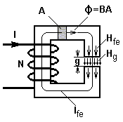
Choking coils and the transformer of the flyback converter must store energy. The stored energy is stored as magnetic field-energy in the ferrite-core, more exactly: stored in the air-gap.The energy which has to be stored amounts to:
![]()
The values L and Imax have been determined on the simulation side.
In order to choose a suitable core, the following requirements for the core must be considered,
- that the magnetic energy storage capacity is at least as big as the above calculated energy ½ ·L I2max and
- that the core is as small as possible, so that it is inexpensive.
The core table for the selection of suitable cores includes 11 columns, and 12 for the flyback transformer. These are:
- NO.: current number to the list of different cores
- Core: Core type
- Identification: Further identification-charictoristics, e.g. air-gap, material or order code
- Manufacturer: Manufacturer of the core, so more information about the core can be requested if required
- AL/NH: The magnetic conductance. With this one can calculate the number of turns needed for L.
- Ae/mm2: The effective magnetic cross section of the core.
- le/mm: The effective magnetic length of the core.
- Amin/mm2: Minimal core cross-section to calculate the maximum magnetic flux-density.
- Wmax/mWs: The magnetic energy storage capacity of the core, for a maximum magnetic flux density of 0.3T
- Bmax/mT: The maximum magnetic flux density in the core. This magnetic flux density is calculated for the worst case scenario within the input voltage range Vin and nominal load. It is calculated for the minimal cross-section area of the core Amin. The maximum flux density is given as an additional important piece of information in order to help the user to select a suitable core. In order to influence Bmax you can change L or ΔIL on the simulation-side.
- N1: The number of turns for the required inductance L, as well as for L1 of the flyback converter.
- N2: The secondary number of turns required for the flyback converter. This column only appears if a flyback converter is calculated. To change the secondary number of turns you can change the ratio N1/N2 on the simulation side. If the ratio is changed it will influence the maximum drain-source voltage of the transistor. The lower the ratio N1/N2 the smaller the drain-source voltage of the transistor Vds_max will be.
The program suggests suitable cores:
- Green writing: Very well-suited cores, whose magnetic energy storage capacity Wmax exceeds the required value by a marginal quantity and also has the smallest possible core-volume. The maximum flux-density in these cores approximately reach the saturation point of 0.3T.
- Brown writing: Well suited cores, whose magnetic energy storage capacity clearly lies over the required value. Its core-volume is up to twice as large as the smallest very-well suited core. The maximum flux density for these cores usually lie between 0.2...0.25T.
- Black writing: Suitable cores, whose magnetic energy storage capacity lie very far over the required value. These cores are uneconomically large.
- Gray writing: Inappropriate cores. Under the condition that Bmax < 0.3T at every point in the core, the magnetic energy storage capacity lies under the necessary value. The column "Bmax/mT" gives information about the actual maximum flux density. If the core material chosen by you has a higher flux density capibility, you can use this core at your own discretion.
Cores can also be added:
Under the core table are seven input-fields. The fields 'core', 'ID' and 'manufacturer', all serve for the identification of the core and are irrelevant for calculations in the program. The fields 'Al', 'Ae', 'le', and 'Amin' must be filled corresponding to the data sheet. To complete your input click "ADD". The inputed core will be added to the table and treated in the same way as the rest of the pre-determined cores in the table.
Note:
The Wire-diameters proposed by us as well as the Wire-cross-section is always for a declared current density of 3A/mm2.
Calculation of choking-coils and flyback transformers


