High Frequency Transformer Design
Use of the transformer-core-tables
The high-frequency transformers are calculated with the help of the effective core volume Ve and the minimum core-cross-section Amin. For a required power output Pout = Vout · Iout and a chosen switching frequency f a suitable core volume Ve must be determined. Then an optimal ΔB is selected depending on the chosen switching frequency and also regarding the temperature rise of the transformer.
(see [2], [3]).
The program makes suggestions for
- very well-suited cores (Green writing), whose volume lies between the value which was calculated by us to be suitable for the required power transfer, and 50% over that value. This volume is chosen such that the transformer temperature rise during operation is under 30K and the coil with a current density S = 3A/mm2 fits into the available winding area.
- well suited cores (Brown writing), whose volume lies between 50% and 100% over the value recommended by us,
- suitable cores (Black writing), whose volume is greater than 100% over the value recommended by us (thus being uneconomically large),
- inappropriately small cores (Gray writing), whose volume is below the value recommended by us. However, this does not mean that the core would be unsuitable. By reducing the primary number of turns N1 you can adapt the magnetic flux density and the winding area to your request. However in this case they will have a higher temperature rise than the cores indicated in green.
You can change the suggested value for the primary number of turns N1 according to your desires (the modification must be concluded with "return"). In each case a new value for ΔB will be displayed in the corresponding column. This also results in a change of the number of secondary turns N2 such that the ratio N1/N2 will not be affected. The turns ratio N1/N2 can only be changed on the simulation side.
The wire-diameter proposed by us as well as the wire-cross-section is always calculated for a current density of S = 3A/mm2. If you change the number of primary turns, it can happen that the wire cross-section proposed by us no longer fits into the winding area, especially if you choose a smaller core (Gray writing), than the one suggested by us.
Top of page
Design of HF transformers
High frequency transformers transfer electric power. The physical size is dependent on the power to be transfered as well as the operating frequency. The higher the frequency the smaller the physical size. Frequencies are usually between 20 and 100kHz. Ferrite is mainly used as the core material.
Data books for appropriate cores provide information about the possible transfer power for various cores.
The first step to calculate a high frequency transformer is usually to choose an appropriate core with the help of the data book which provides certain tables for this purpose. Another way to choose an appropriate core is described in
[1] and [2] where at first a core-weight or core-volume is determined depending on the transfer power and switching frequency.
In the second step, the primary number of turns is calculated because this determines the magnetic flux-density within the core. Then the wire-diameter is calculated, which is dependent on the current in the primary and secondary coils.
Top of page
Calculation of the minimum number of primary turns:
|
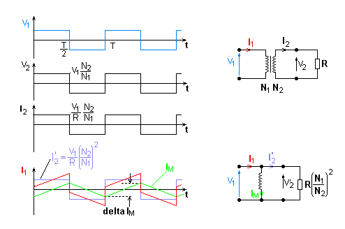
| Illustration 1: Voltages and currents of the transformer
|
It is assumed that there is a square-wave voltage V1 at the primary side of the transformer. This causes an input current I1, which consists of the back transformed secondary current I2 and the magnetising current IM (see illustration 1). A core without an air-gap is used in order to keep the magnetising current as small as possible.
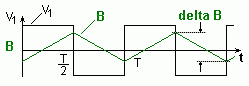
The square-wave voltage at the input of the transformer causes a triangular shaped magnetising current IM which is almost independent of the secondary current (see also the equivalent circuit). The magnetising current is approximately proportional to the magnetic flux Φ i.e. to the magnetic flux density B. The input voltage V1 determines the magnetic flux in the transformer core corresponding to Faraday's Law V = N · d(Φ)/dt (see illustration 2).
|
Illustration 2: Input voltage and magnetic
flux density of the transformer
|
For the transformer on the right in the diagram above, the following applies:
- The change ΔB of flux-density depends on the frequency f = 1/T and the number of turns N1. The higher the frequency and the number of turns the lower the change of flux density.
Now the minimum number of turns N1 can be calculated to ensure that a certain change of flux-density ΔB is not exceeded. The saturation flux density of +/-0.3T, (which means ΔB = 0.6T) cannot be used normally for high frequency transformers. In Push-Pull converters going around the hysteresis loop with every clock cycle would cause unacceptable losses, i.e. heat generation. If no further information concerning core losses and thermal resistance is available, ΔB should be limited to ΔB = 0.3...0.2T with usual frequencies (20kHz to 100kHz). Further information concerning the selection of ΔB can be found in
[1] and [2].
- In general the following applies: the smaller the change in flux-density ΔB, the smaller the hysteresis losses.
From this a suitable number of turns for N1 results:
(Where Amin is the minimum core cross-section. This determines the maximum flux density. Amin is given in the data-sheet)
Note:
With single transistor forward converters, the core is magnetised in one direction only, while with the push pull converter it is magnetised in both directions. If the core is used up to the saturation level, the maximum change in flux density with the push-pull converter may be 0.6T and may amount to 0.3T for the single transistor forward converter, if usual ferrites are used.
Top of page
Calculation of the wire-diameter:
The wire-diameter depends on the respective r.m.s. value of the coil current. This can be calculated from the coil power. If the losses are neglected and it is assumed that with Vin_min
the maximum duty cycle is achieved, it follows that:
- For the Single Transistor Forward Converter:
- For the Full Bridge Push-Pull Converter:
- For the Half Bridge Push-Pull Converter:
In the above calculations the magnetising current can be neglected. The current density S is chosen between 2 and 5 A/mm2, depending on the thermal resistance. The wire cross-section Awire and the wire diameter dwire can be calculated as follows:
Usual cores are designed such that the above calculated coil fits into the available winding area. Primary and secondary windings both need an equal amount of the winding area.
Note:
For high frequencies and large wire-diameters, the skin-effect must be taken into account. It is recommended to use copper-foil or HF-wire for frequencies > 20kHz and wire-cross-sections > 1mm2.
Top of page
Tips
- Do not alter the turns ratio N1/N2.
- A reduction in the number of turns N1 will cause an increase in ΔB and a quadratic increase of hysteresis losses.
- Cores, whose effective core volume Ve lie marginally below the value suggested by us, can be suitable if one allows a higher temperature. However the resulting core temperature can only be determined properly in an experiment.
- Pay attention not to exceed the saturation levels of ΔB when varying the number of turns (ΔBmax = 0.3T for the Two Transistor Forward Converter and ΔBmax = 0.6T for the Push-Pull Converter).
- The number of turns N2 can only be altered on the simulation side by altering the turns ratio N1/N2. An alteration, which would prevent the required output voltage from being reached for Vin = Vin_min, will be rejected by the program.