Buck Converter
| Main page | | How to use the program | | Function principals | | Mathematics used in the program | | |
| Top of page | | Application | | Tips | | Literature Notes | | Help for choking coils |
How to use the program
Reference: The shapes of current and voltage curves are calculated using Faraday's Law. They do not represent an incremental simulation like it is done normally by programs like P-Spice. In the calculations the forward voltages of the diodes are considered with VF = 0.7V, and the transistors are interpreted as ideal switches.
Application:
The Buck Converter converts an input voltage to a lower output voltage. The buck converter often replaces the traditional analogue voltage regulator.
Function principals
|
|
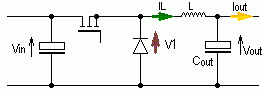
| Illustration 1: Buck Converter |
For the following analysis it will be assumed that the transistor is simplified as an ideal switch and the diode has no forward voltage drop. In the program itself, the diode will take into account a forward voltage drop VF = 0.7V.
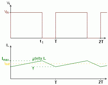
During the on-time of the transistor, the voltage V1 is equal to Vin. Since Vin is higher than Vout the current through the diode increases linearly in correspondence to Faraday's Law.
When the transistor is turned off (blocking phase) the diode takes the inductor current. At this time the voltage across the inductor inverts. The voltage V1 becomes zero (exact: -0.7V) and the voltage across the inductor is now -Vout. The inductor current IL
decreases linearly. If the current IL does not decrease to zero during the blocking phase, this is called continuous mode (see illustration 2).
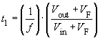
In this mode V1 is a voltage which changes between Vin and zero, corresponding to the duty cycle t1/T. The Low Pass Filter, formed by L and Cout, produces an output voltage equivalent to the average value of V1, i.e. Vout = V1.
![]()
The inductor current IL has a triangular shape, its average value is determined by the load. The peak to peak current ripple ΔIL is dependent on L and can be calculated with the help of Faraday's Law. For Vout = (t1/T) · Vin and a switching frequency f it follows that for continuous mode:
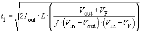
At low load current, namely if Iout < ΔIL/2, the inductor current IL falls to zero during every switching cycle. This mode is called discontinuous mode (see illustration 2). For this mode the calculations above are not valid.
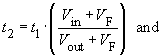
At the moment when the inductor current becomes zero, i.e. t2, the voltage V1 jumps to the value of Vout because in this case VL = 0. The drain-source capacitance in parallel with the diode-junction capacitance forms a resonant circuit with the inductance L. This is stimulated by the voltage jump across the diode. The voltage V1 then oscillates and fades away.
|
|
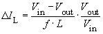
Continuous Mode | Discontinuous Mode |
Illustration 2: Operating modes of the Buck Converter
Vin_min, Vin_max, Vout, Iout and f
Using these parameters, the program produces a proposal for L:
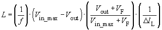
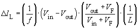
From this it follows that:
 ,
,
| Main page | | How to use the program | | Function principals | | Mathematics used in the program | | |
| Top of page | | Application | | Tips | | Literature Notes | | Help for choking coils |