Buck Boost Converter

Main page | How to use the program | Function principals | Mathematics used in the program |
Top of page | Application            | Tips              | Literature Notes                | Help for choking coils

How to use the program

Reference: The shapes of current and voltage curves are calculated using Faraday's Law. They do not represent an incremental simulation like it is done normally by programs like P-Spice. In the calculations the forward voltages of the diodes are considered with VF = 0.7V, and the transistors are interpreted as ideal switches.

Top of page

Application:

The Buck-Boost Converter converts a positive input voltage to a negative output voltage. With a Buck-Boost converter one could create a -12V potential from a 5V source.

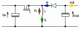
Illustration 1: Buck Boost Converter

Top of page

Function principals:

The transistor works as a switch, which is turned on and off by the pulse-width-modulated control voltage. For the analysis of the following circuit it may be assumed that the transistor and the diode have no voltage drop during the respective on-phases. In the program the diode forward voltage of VF = 0.7V is taken into account.

During the on-time of the transistor, there is an input voltage Vin applied across the inductor L. The inductor current IL increases linearly. Energy is loaded into the inductor.

During the blocking phase of the transistor, the current IL continues to flow through the inductor and loads the output capacitor Cout. The inductor transfers its energy to Cout.

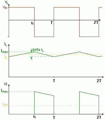
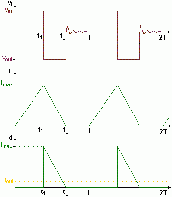
One can make a distinction between continuous and discontinuous mode depending on whether the inductor current IL goes to zero or not.
For continuous mode using Faraday's Law gives:

Eqn 1

From this it follows that:

Eqn 2

In discontinuous mode the inductor current falls to zero during every period. At that moment when the current becomes zero, the voltage VL also goes to zero. The drain-source capacitance in parallel with the diode-junction capacitance together with the inductor L, creates a resonant circuit which is activated by the voltage jump of V1. The voltage VL then oscillates and fades away.

Continuous Mode

Discontinuous Mode

Illustration 2: Operating modes of the Buck Boost Converter

Top of page

Tips

Top of page

Mathematics used in the program

The following parameters must be entered into the input fields:

Vin_min, Vin_max, Vout, Iout and  f 

Using these parameters, the program produces a proposal for L:

For the calculation of the curve-shapes, and also for the calculation of "ΔIL for Vin_max", two cases have to be distinguished, i.e. continuous mode and discontinuous mode:

Eqn 3.2

Eqn 3.3

From this it follows that:

  1. For ΔIL< 2IL the converter is in continuous mode and it follows that:

    Eqn 4.0,

    Eqn 4.1

    Eqn 4.2


  2. For ΔIL> 2IL the converter is in discontinuous mode and it follows that:

    Eqn 5.0,

    Eqn 5.1

    Eqn 5.2


Main page | How to use the program | Function principals | Mathematics used in the program |
Top of page | Application            | Tips              | Literature Notes                 | Help for choking coils