Power Factor Pre-regulator

Main page | How to use the program | Function principals           | Calculation of the Inductor         | Literature Notes          
Top of page | Application            | Currents, Voltages and Powers | Calculation of the output Capacitor | Help for choking coils

How to use the program

Top of page

Application:

The European standards EN61000-3-2 define limits for the harmonics of the line current. This concerns appliances, which may be sold to the general public and have an input power of > 75W (special regulations see EN61000-3-2). Some limit values from this standard are given in the following table.

Harmonic-
order
n
Input Power 75 to 600W
Allowable maximum value of
harmonic current
per Watt (mA/W) / maximum (A)
Input power > 600W
maximum value of
harmonic current
(A)
3 3.4 / 2.30 2.30
5 1.9 / 1.14 1.14
7 1.0 / 0.77 0.77
9 0.5 / 0.4 0.40
11 0.35 / 0.33 0.33

In practice this standard means that for many applications a mains rectifier with smoothing is not allowed because of the amount of harmonics (see Illustration 1).

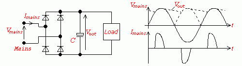
Illustration 1: Direct half-wave rectification:
The mains has high upper harmonic content

The Power Factor Pre-regulator is a switch mode power supply which is connected in front of the voltage stabilizing SMPS in order to keep the line current approximately sinusoidal. The Power Factor Pre-regulator is also commonly known as a PFC, which stands for Power Factor Correction.

Top of page

Function principals

In order to keep the line current approximately sinusoidal, a boost converter can be used (see Illustration 2). In this case the boost converter is called a Power Factor Pre-regulator (PFC).In comparison to the boost converter the PFC is controlled in a different way: The output voltage is higher than the maximum input voltage as for the boost converter (this is 360V in the European mains), but the transistor is turned on and off in a way, such that a sinusoidal input current is achieved instead of an exact constant output voltage. This is achieved by means of a certain switching method. By means of a suitable regulator, the inductor current is driven such that it is proportional to the shape of the input voltage |Vin|. The inductor current IL follows, in a 'saw-tooth' fashion, the shape of the sinusoidal input voltage. The saw-tooth current ripple can be reduced by enlarging the inductance or by increasing the switching frequency. However, the inductor value may not be increased such that the current-slope diL/dt could not follow the sinusoid. The output voltage of the power factor pre-regulator is usually regulated to an average value of Vout = 380VDC with Vin = 230VAC.

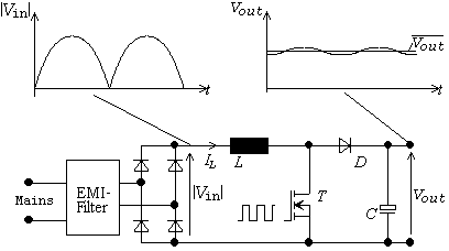
Illustration 2: Boost Converter as Power Factor Pre-regulator

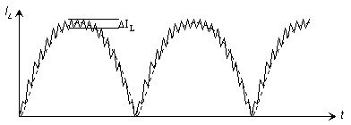
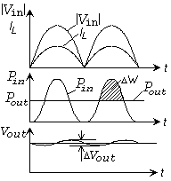
Illustration 3: The inductor current IL

Top of page

Currents, Voltages and Powers

For the following analysis it will be assumed that the inductor current is a pulsating sinusoid (the superimposed saw tooth current ripple is neglected), and is in phase with the input voltage Vin. The output voltage is a constant DC voltage because of the very high value output capacitor C. The output power is constant for the considered time interval. Illustration 4 shows the voltage, current and power curves of the PFC in the time domain.

For the output power Pout this leads to:

Eqn 1.0

and for the input power Pout(t):

Eqn 1.1

The input power consists of a DC component

Eqn 1.2

and an AC component

Eqn 1.3

The DC component is equal to the output power Pout:

Eqn 1.4

The PFC is taken to be loss free but actually an efficiency of 95% is realistic.

With this efficiency, the input power emerges to:

Eqn 1.5

The r.m.s. value of the input current has its maximum when the input voltage is at its minimal value, i.e. minimal mains voltage:

Eqn 1.6

This value will be required for the calculation of the inductor current later.

Illustration 4:
Time frame course of the currents,
voltages and powers in the
Power Factor Pre-regulator

Calculation of the inductor L:

The PFC operates in continuous mode. The magnitude of the current ripple due to the switching is called ΔIL.

The current ripple amounts to (see Boost Converter):

Eqn 2.0

For L it follows that:

Eqn 2.1

Usually, one chooses:

Eqn 2.2

The maximum inductor current then amounts to:

Eqn 2.3

Top of page

Calculation of the output capacitor C:

The output voltage ripple will be calculated with the help of a power balance. It is assumed that the PFC is loss free. The output capacitor is charged by the pulsating input power and discharged by a constant output power, (see illustration 4). The output power is equal to the average of the input power. The AC component of the input power causes the voltage ripple ΔVout.
This leads to:

Eqn 3.0

Eqn 3.1

Through integration, for ΔW, it follows that (see illustration 4):

Eqn 3.20

Eqn 3.21

This implies:

Eqn 3.30

The magnitude of the voltage ripple ΔVout caused by ΔW, depends on the output voltage.

Eqn 3.31

Eqn 3.4

For the voltage ripple ΔVout it follows that:

Eqn 3.5

as well as for the output capacitor C:

Eqn 3.6

Usually, one chooses ΔVout = 5% of Vout = 380V. This results in a voltage ripple of +/- 10V. For 50/60Hz - mains it follows that the output capacitor should be: C = 0.5µF/W


Main page | How to use the program | Function principals           | Calculation of the Inductor         | Literature Notes          
Top of page | Application            | Currents, Voltages and Powers | Calculation of the output Capacitor | Help for choking coils