Flyback Converter
How to use the program
Reference: The shapes of current and voltage curves are calculated using Faraday's Law. They do not represent an incremental simulation like it is done normally by programs like P-Spice. In the calculations the forward voltages of the diodes are considered with VF = 0.7V, and the transistors are interpreted as ideal switches.
- The values of all input fields can be changed.
- If an input field is left empty, a default value is chosen. This value is displayed after leaving the input field in question.
- The switch mode power supply operates within a certain input range i.e. between Vin_min and Vin_max.
Note:
- For the european mains of 230V +/-10% and behind the rectifier and the smoothing (with a voltage ripple of 10%) the input voltage range is between Vin_min = 250V and Vin_max = 360V.
- For wide range Switch Mode Power Supplies the input voltage range of the mains is from 100Vac -10% (Japan) to 240Vac +6% (Great Britain). In this case, the DC input range of the power supply is from Vin_min = 110V to Vin_max = 360V.
- For use of a power factor pre-regulator the input voltage range is normally from Vin_min =360V to Vin_max =400V.
- The program needs the output values Vout and Iout.
- The switching frequency f is the operating frequency of the transistor.
- If the field "proposal" is activated for the primary inductance L1 the value for L1 is proposed. This is such as the border between continuous and discontinuous mode is achieved for the average input voltage which is Vin_avg = (Vin_max+Vin_min)/2.
- If the field "proposal" for the input field "N1/N2" is activated, the turns ratio N1/N2 is proposed. It is proposed such that N1/N2 = Vin_avg/Vout, where Vin is the average value of input voltage range. This means that for the average input voltage, the maximum voltage across the transistor is Vds = 2Vin_avg.
- If you do not agree with our proposals, you can change N1/N2 or L1. The field "proposal" is then deactivated automatically.
- The value Vin is the value for the calculation of the current and voltage diagrams on the right side of the display. Vin must lie between Vin_min and Vin_max.
Note 2: The calculations are made for an efficiency of 1. This is actually not realistic for a flyback converter. The efficiency is determined mainly by the coupling of the primary and secondary winding. If the number of turns N1 and N2 are very different (normally the case with low output voltage), then the coupling between primary and secondary will be bad and this leads to a low efficiency of about 65-70%. If the number of turns N1 and N2 are approximately equal, then you will reach a good coupling and the efficiency can be > 90%. To reach a realistic result for the primary current I1 and the primary inductor L1, you should increase the output current by a realistic factor 1/η for the efficiency.
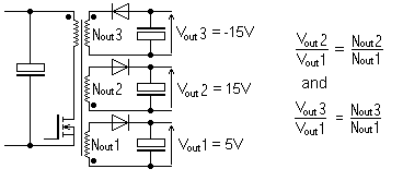
Note 3: The flyback converter may have several separately isolated output voltages which are all regulated, e.g +5V, +15V, -15V. In this case only one of the output voltages has to be regulated (e.g. +5V) and the other output voltages are coupled by their number of turns in respect to the regulated output voltage.
|
To calculate such a case with our program you should add all output powers and make the calculation for one output voltage by relating it to the sum of all output powers (e.g.Vout_1). If an appropriate core with an appropriate number of secondary turns is calculated, you have to add the uncalculated turns of the other output voltages by calculating the number of turns using the ratio of the voltages (in our example Nout_2 and Nout_3 ).
Top of page
Application
The Flyback Converter belongs to the primary switched converter family, which means there is isolation between input and output. Flyback converters may have several separately isolated output voltages which are regulated by controlling only one output voltage. Today flyback converters are used in many mains supplied electronic devices of small power consumption (up to 250W) e.g. Television sets.
Top of page
Function principals
|
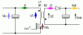
| Illustration 1: Flyback Converter
|
Flyback converters have a remarkably low number of components compared to other SMPS's. They also have the advantage that several isolated output voltages can be regulated by one control circuit.
The transistor works as a switch which is turned on and off by a pulse-width-modulated control voltage.
During the on time of the transistor, the primary voltage V1 = Vin and I1 increases linearly.
During that phase energy is loaded into the transformer.
The secondary winding does not have any current because the diode is blocking during the on-time of the transistor.
If the transistor is in blocking mode then I1 will be cut-off and the voltages at the transformer will change because of Faraday's Law.
The diode will then be conducting and the secondary winding will then give energy to the output capacitor.
During the on-phase of the transistor the drain-source-voltage Vds will be zero.
During the off-phase the output voltage is back transformed to the primary side such that the drain-source voltage achieves the value Vds = Vin + Vout·N1/N2.
This implies that for a flyback converter which is designed for a 230V/50Hz mains, the voltage Vds usually reaches approximately 700V. In practice the voltage is even higher because an induction voltage is added as a result of transformer leakage induction. The transistor in the flyback converter for the 230V mains must have a breakdown voltage of at least 800V.
The transformer is not a "normal" transformer. Its function is to save energy during the on-phase of the transistor and to transfer that energy to the secondary side during the off-phase. This means that the transformer is a storage-inductor with primary and secondary windings and the transformer-core has an air-gap. Transformers for flyback converters are therefore called storage transformers.
In order for the stored energy of the primary current to be transferred to the secondary winding during the off-phase of the transistor, both coils must be very well magneticly coupled.
| 
|
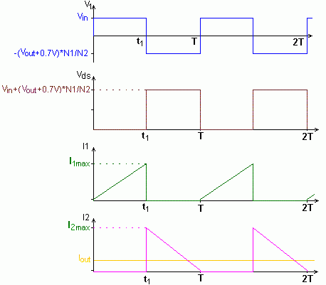
Continuous Mode
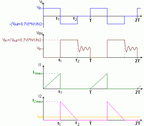
| Discontinuous Mode
|
Illustration 2: Operating modes of the Flyback Converter
Top of page
Tips
- The larger the number of turns N2 the smaller the drain-source voltage of the transistor Vds.
- At the border between continuous and discontinuous mode at Vin = Vin_min the size of the transformer will be at its smallest. However, in this case the flyback converter works in discontinuous mode with all other input voltages. As a result of this the switching-losses through the semiconductors become quite big.
- The drain-source voltage of the transistor Vds is at its highest when Vin = Vin_max.
Top of page
Mathematics used in the program
The following parameters must be entered into the input fields:
Vin_min, Vin_max, Vout, Iout and f
Using these parameters, the program produces a proposal for L and N1/N2:
For the calculation of the curve-shapes, and also for the calculation of "ΔIL for Vin_max", two cases have to be distinguished, i.e. continuous mode and discontinuous mode:
From this it follows that:
- For ΔIL1< 2I'1 the converter is in continuous mode and it follows that:
 ,
,
- For ΔIL1> 2I'L1 the converter is in discontinuous mode and it follows that:
 ,
,